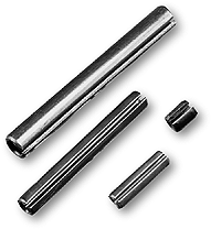
Spring Roll Pins
These pins feature hollow cylinders slit longitudinally permitting compression during insertion. Designed to replace Taper pins, straight pins, and set screws, they will also serve as a rivet, dowel, hinge pin or cotter pin in many applications. Made of 1070 carbon spring steel hardened to Rockwell 45-50, tempered and oiled, They can be doubled up for heavy duty applications (See Chart). Plain or plated finishes available as well as stainless steel. Stocked in lengths to fit holes from .062" to .510".
Group codes Represented: SRP
Part# Example: 43100SRP, M220SRP
Double
Up For Heavy Duty Applications |
|||||||
Use
one standard inside another for additional strength. Install the
smaller pin inside the larger pin, then insert into the application. |
|||||||
Pin |
Diameter |
||||||
Inside |
3/32 |
1/8 |
5/32 |
3/16 |
7/32 |
5/16 |
|
Outside |
5/32 |
7/32 |
1/4 |
5/16 |
3/8 |
1/2 |
|

Spring
Pins, Slotted Type |
|||||||||||
Nominal
Size or Basic Pin Diameter |
G |
H |
C |
T |
Recommended
Hole Size |
Double
Shear Load, Min, lbs. |
|||||
Pin
Diameter |
Chamfer
Dia. |
Chamfer
Length |
Wall Thickness |
||||||||
Max* |
Min** |
Max |
Max |
Min |
Basic |
Max |
Min |
SAE 1070-1095
steel & 420 Stainless |
300 series
Stainless |
||
1/16 |
0.062 |
0.069 |
0.066 |
0.059 |
0.028 |
0.007 |
0.012 |
0.065 |
0.062 |
430 |
250 |
5/64 |
0.078 |
0.086 |
0.083 |
0.075 |
0.032 |
0.008 |
0.018 |
0.081 |
0.078 |
800 |
460 |
3/32 |
0.094 |
0.103 |
0.099 |
0.091 |
0.038 |
0.008 |
0.022 |
0.097 |
0.094 |
1150 |
670 |
1/8 |
0.125 |
0.135 |
0.131 |
0.122 |
0.044 |
0.008 |
0.028 |
0.129 |
0.125 |
1875 |
1090 |
5/32 |
0.156 |
0.167 |
0.162 |
0.151 |
0.048 |
0.010 |
0.032 |
0.160 |
0.156 |
2750 |
1600 |
3/16 |
0.188 |
0.199 |
0.194 |
0.182 |
0.055 |
0.011 |
0.040 |
0.192 |
0.187 |
4150 |
2425 |
7/32 |
0.219 |
0.232 |
0.226 |
0.214 |
0.065 |
0.011 |
0.048 |
0.224 |
0.219 |
5850 |
3400 |
1/4 |
0.25 |
0.264 |
0.258 |
0.245 |
0.065 |
0.012 |
0.048 |
0.256 |
0.250 |
7050 |
4100 |
5/16 |
0.312 |
0.330 |
0.321 |
0.306 |
0.08 |
0.014 |
0.062 |
0.318 |
0.312 |
10800 |
6300 |
3/8 |
0.375 |
0.395 |
0.385 |
0.368 |
0.095 |
0.016 |
0.077 |
0.382 |
0.375 |
16300 |
9500 |
7/16 |
0.438 |
0.459 |
0.448 |
0.43 |
0.095 |
0.017 |
0.077 |
0.445 |
0.437 |
19800 |
11500 |
1/2 |
0.500 |
0.524 |
0.513 |
0.485 |
0.110 |
0.025 |
0.094 |
0.510 |
0.500 |
27100 |
15800 |
*Maximum
diameter shall be checked using a "GO" ring gauge. |
|||||||||||
**Minimum
diameter shall be equal to average of three diameters measured
at points as illustrated above |
|||||||||||
G
min. = G1+G2+G3 / 3 |
|||||||||||
Tolerance
on Length |
Nominal
Pin Length |
||||||||||
Up to 1 in., Incl. |
Over 1 to 2in., Incl. |
Over 2 to 3 in., Incl. |
Over 3 to 4 in., Incl. |
||||||||
±0.015 |
±0.020 |
±0.025 |
±0.030 |
||||||||

